Receiver

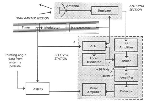
To accomplish the conversion, the mixer must be supplied with a continuous-wave (CW) signal from an RF oscillator called the "local oscillator" (LO). The power required from this oscillator is only a few milliwatts, and it must operate at a frequency close to that of the transmitter. The output of the mixer contains the sum and difference frequencies of the two inputs, but the difference frequency is selected as the intermediate frequency of the receiver. Intermediate frequencies commonly used in radar systems are 30 MHz and 60 MHz.
As the IF amplifier is designed to operate at a fixed
frequency, the difference between the transmitter and local oscillator
frequencies must be maintained at a constant value equal to the desired
IF. In radars with magnetron transmitters, a servomechanism is used to
adjust the local oscillator frequency so as to maintain the proper
difference. This is called an "automatic frequency control" (AFC)
system, and it operates by sampling each transmitted pulse and
comparing its frequency with that of the local oscillator. If the
difference is not equal to the desired intermediate frequency, the AFC
system adjusts the local oscillator frequency to obtain the proper
value.
In radars with klystron transmitters, no automatic
frequency control is needed because the transmitter frequency is
derived from the local oscillator frequency by a heterodyning process
that maintains a constant difference between the two.
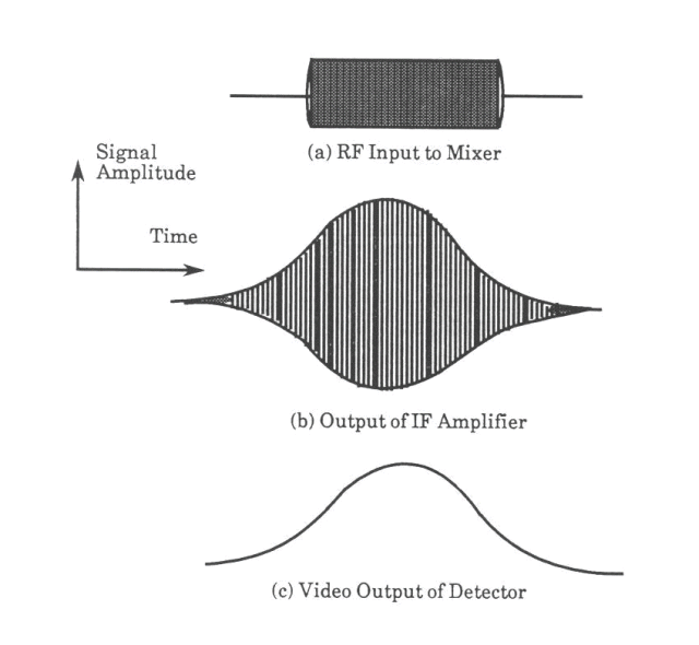
The waveform shown in the bottom figure (a) represents an echo as it might appear before the signal enters the mixer. The IF component in the output of the mixer is amplified by the IF amplifier (top figure) to a level suitable for subsequent processing. At the output of the IF amplifier, the echo still consists of modulated sine waves, but the frequency of the sinusoidal oscillations is now the intermediate frequency instead of the radio frequency. Moreover, the shape of the "modulation envelope" containing the oscillations is usually altered somewhat because of the response characteristics of the IF amplifier. These changes are illustrated by (b).
The sinusoidal oscillations within the echo in (a) and (b) are of no interest to the user of a pulse radar system, because the information about the presence and location of the target is contained in the amplitude or modulation envelope of the echo.
