Azimuth Distortion and Resolution
To understand the concept of azimuth distortion (also referred to as “beam width distortion”), a knowledge of the definition of the radar beam is imperative. The beam is defined such that, in most cases, any meteorological target (precipitation) with which it comes in contact will backscatter a detectable amount of energy to the radar. What will the radar display as it scans through a target in azimuth?
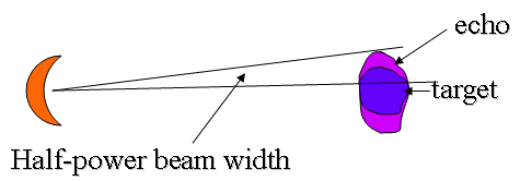
Figure 1. Azimuth distortion in the horizontal plane
It is apparent that azimuth distortion will result in an enlargement of a target by approximately one-half beam width on either side, so total enlargement is equal to one beam width. Azimuth distortion is the most significant contributor to overestimation of precipitation coverage by radar. Azimuth distortion increases as a function of range (see figure 1).
Echo enlargement is not restricted to the PPI display, however. As you scan upward in RHI mode in an attempt to determine the base and top of a target, the echo will be stretched by one-half beam width above and below. This is why a half-beam width correction should be applied when determining tops and bases of echoes. The range of the storm must be known before this can be done properly.

Azimuth resolution = one beamwidth
Since azimuth distortion stretches targets by one-half beam width on either side, two echoes at the same range from the radar must be at least one beam width apart in order to be detected separately. This minimum separation in azimuth necessary for targets to be resolved individually defines the azimuth resolution (also called “beam width resolution”).

Figure 3. Azimuth distortion on the radar display
For a beam width of 1.6 degrees azimuth distortion is approximately 1.5 km at 50 km range, half on either side of the target. That is, at a range of 50 km, two cells must be more than 1.5 km apart to appear as two echoes on the scope. Similarly, at 300 km range, azimuth distortion is about 8 km. That is, two cells must be more than 8 km apart to appear as two echoes on the scope.
Azimuth distortion results in targets separated by less than a beamwidth appearing as one echo. So two separate echoes would be seen as one elongated echo at further distance.