Velocity Azimuth Display (VAD)
Although a Doppler radar only measures the radial component of target velocity, techniques have been developed in order to determine true wind speed and direction. Lhermitte and Atlas (1961) proposed a technique which is very useful when a Doppler radar is surrounded by scatterers having uniform motion. This is the Velocity-Azimuth display (VAD) which utilizes an azimuthally scanning beam at one or more elevation angles.
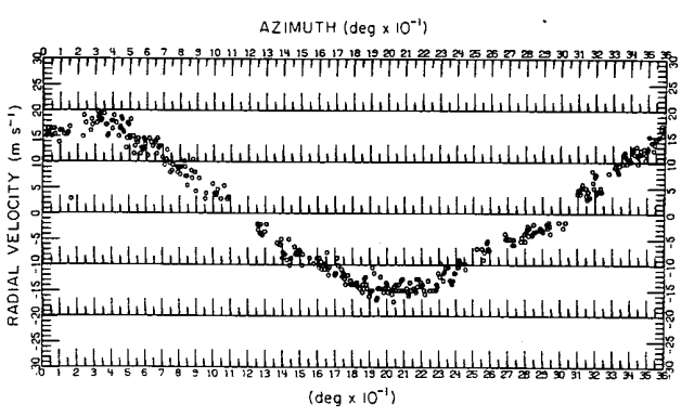
Since the radial outflow is positive and radial inflow is negative it is evident the wind direction can be obtained directly from such a display.
By scanning at a number of elevation angles and ranges, vertical wind profiles can be derived. These will be volume averages where the range and elevation chosen will determine the size of the volume.
It is evident that if the maximum upwind radial velocity
does not equal the corresponding maximum on the downwind side then
convergence or divergence must be occurring. Techniques have been
developed to analyse VAD winds in more detail to yield such estimates.
Reference is made to Doviak and Zrnic (1985) for more on this subject.
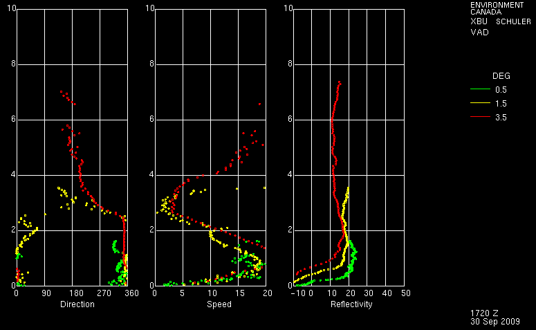
For each of the 3 Doppler scans (shown in green yellow and red) a best fit sine curve is applied to all the available radial velocity data for each range. And from this an estimate of wind direction and speed can be produced. Since range corresponds to height for a given elevation angle, plots of speed and direction with height can be made. Also plotted is reflectivity averaged around a range bin and then converted to height.